Description.
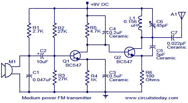
This is the circuit diagram of a moderate power FM transmitter circuit employing two transistors.The voice signals picked by the microphone will be amplified by the transistor Q1.The second transistor is wired as an oscillator operating in the FM band.The output of T1 is given to the base of T2.T2 performs the modulation also.The tank circuit comprising of components L1 and C6 determines the frequency of the signal, and can be varied by adjusting C6.The capacitor C7 couples the FM signal to the antenna.
Circuit diagram with Parts list.This is the circuit diagram of a moderate power FM transmitter circuit employing two transistors.The voice signals picked by the microphone will be amplified by the transistor Q1.The second transistor is wired as an oscillator operating in the FM band.The output of T1 is given to the base of T2.T2 performs the modulation also.The tank circuit comprising of components L1 and C6 determines the frequency of the signal, and can be varied by adjusting C6.The capacitor C7 couples the FM signal to the antenna.

Notes.
- You can assemble the circuit on a general purpose PCB.
- The circuit can be powered from a9V PP3 battery.
- The Antenna A1 can be a 1M long wire.
- The inductor L1 can be made by making 6 turns of 0.8mm enameled copper wire on a 5.5mm diameter/4.5mm length plastic former.
- With a matching antenna and proper tuning this transmitter can have range upto 100meter
Using this low cost Project one can reproduce AUDIO from TV without disturbing anyone. It does not use any wire between TV and HEADPHONE. In place of pair of wires it uses invisible Infrared light to transmit audio signals from TV to Headphone. Without using any lens a range of up to 6 meters is possible. Range can be extended by using Lenses and Reflectors with IR sensors comprising transmitters and receivers. IR transmitter uses two-stage transistor amplifier to drive two IR leds connected in series. An audio output transformer is used (in reverse) to couple Audio output from TV to the IR transmitter. Transistors (BC547) & (BD140) amplify the audio signals received from TV through audio transformer low impedance output windings (lower gauge or thicker wire) are used for connection to TV side while high impedance are connected to the IR transmitter. This IR transmitter can be powered by 9v mains Adaptor or 9v Battery. Led in transmitter circuit functions as power-on indicator. IR receiver uses 3-stage transistors amplifier. The first two transistors (BC549c)from audio signal amplifier. While the third transistor(BD139)is used to drive a headphone. Adjust potmetre for max clarity. Direct photo transistor towards the IR Leds of transmitter for max range. A 9v Battery can be used to receiver circuit for portable operation
.bmp)
.bmp)
.bmp)
No comments:
Post a Comment